NMOS (N-channel Metal-Oxide-Semiconductor) transistors are a type of MOSFET (Metal-Oxide-Semiconductor Field-Effect Transistor) that play a critical role in modern electronics, especially in digital circuits and integrated circuit (IC) design. NMOS transistors are highly valued for their speed, efficiency, and wide range of applications. They are commonly used in conjunction with PMOS transistors to form CMOS (Complementary Metal-Oxide-Semiconductor) technology, which powers most modern processors and memory devices. NMOS technology is the backbone of many digital switching circuits due to its fast switching times and lower resistance when turned on.
Meaning
An NMOS transistor is a type of MOSFET that operates using N-type semiconductor material. In N-type material, electrons are the majority carriers, which means the current flow is based on the movement of electrons, a more efficient process compared to hole-based conduction in P-type materials (as used in PMOS transistors).
The term "N-channel" refers to the formation of an electron-rich conduction channel between the source and drain terminals when a positive voltage is applied to the gate terminal. The "Metal-Oxide-Semiconductor" describes the construction of the transistor, which includes a metal gate (in modern devices, polysilicon is often used instead of metal), an oxide insulator (commonly silicon dioxide), and a semiconductor substrate (typically silicon).
In an NMOS transistor, when the gate voltage is higher than the source voltage, it creates a conductive channel for electrons to flow from the drain to the source, enabling current to pass through the transistor.
NMOS Working Principle
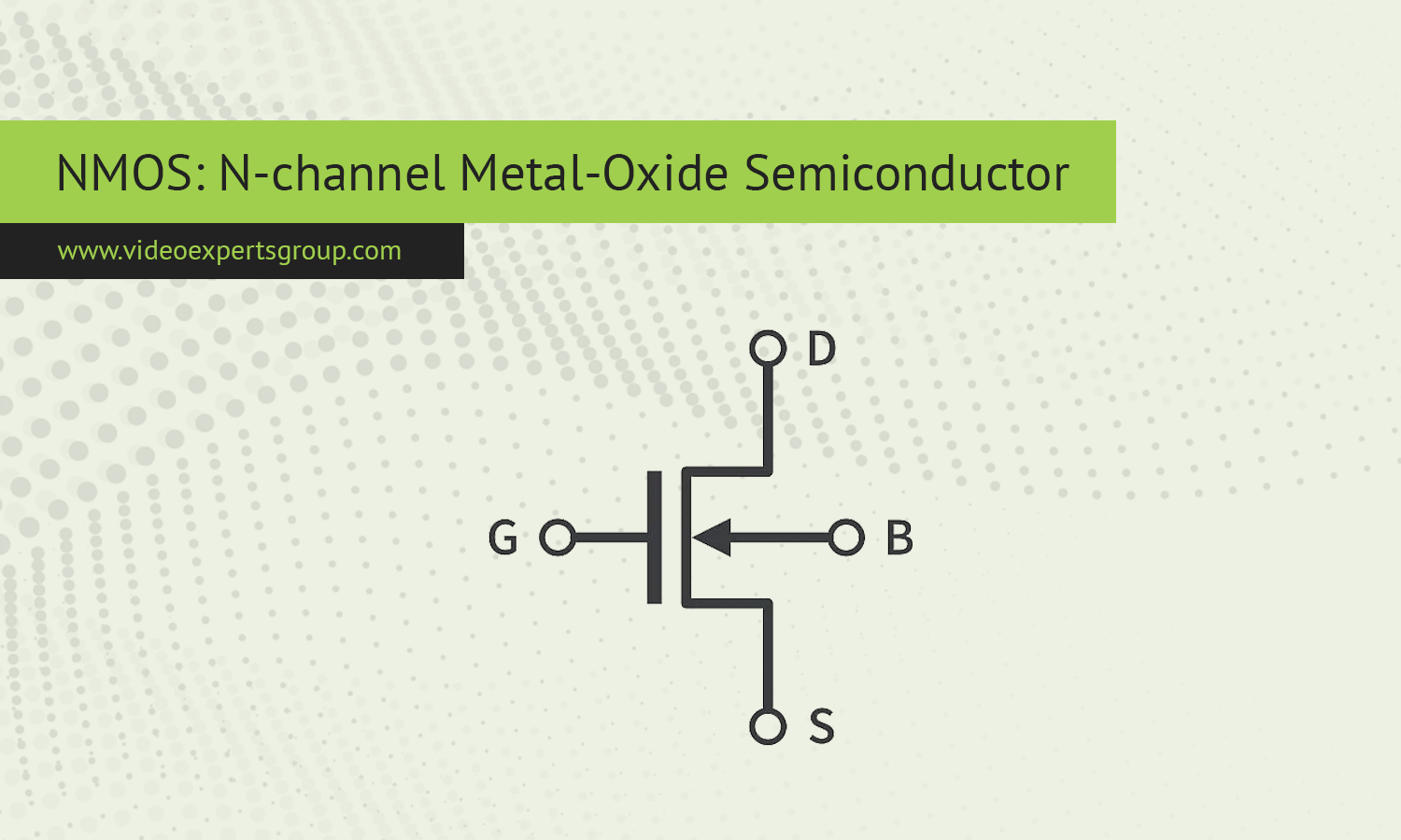
The working principle of an NMOS transistor is based on the ability to control the flow of electrons through the semiconductor channel by applying voltage to the gate terminal. Like all MOSFETs, NMOS transistors have three primary terminals:
- Source (S): The terminal where current enters the transistor.
- Drain (D): The terminal where current exits the transistor.
- Gate (G): The terminal that controls whether the current flows between the source and drain.
The operation of the NMOS transistor can be understood in two states: the "on" state (when the transistor allows current to flow) and the "off" state (when no current flows).
-
Off State (V_GS = 0V): When no voltage is applied to the gate terminal (or when the gate-to-source voltage is below a threshold), the NMOS transistor is in the off state. In this condition, the channel between the source and drain does not exist, and the current flow is blocked. The N-type material remains insulated by the oxide layer, and the electrons are not free to move.
-
On State (V_GS > V_th): When a positive voltage is applied to the gate relative to the source (i.e., exceeds the threshold voltage ), an electric field forms in the semiconductor, attracting electrons to the region under the gate oxide. This creates a conductive N-type channel between the source and drain, allowing electrons to flow from the drain to the source, thus enabling current flow through the transistor. The strength of the channel increases with higher gate voltage, allowing more current to pass.
In summary:
- NMOS transistors turn on when a positive voltage is applied to the gate.
- NMOS transistors turn off when the gate voltage is zero or below a certain threshold.
This behavior is the core of NMOS transistors' switching capabilities, making them suitable for use in digital circuits, where they switch between on and off states to represent binary data (1s and 0s).
NMOS Circuit Diagram
A basic NMOS transistor circuit typically consists of the following components:
- Source (S): The terminal connected to the ground (0V).
- Drain (D): The terminal connected to the load (resistor, LED, etc.) and a positive voltage (V+).
- Gate (G): The terminal where a control voltage is applied to turn the transistor on or off.
Simple NMOS Circuit Example:
   V+ -----> Load -----> Drain

                    |

                    |

                 Source (ground)

                    |

                 Gate (control voltage)
In this circuit:
- The source is connected to ground.
- The load is connected between the drain and the positive supply voltage.
- The gate controls the flow of current through the transistor. When a positive voltage is applied to the gate (relative to the source), the NMOS transistor turns on, allowing current to flow from the drain, through the load, and out to ground.
NMOS transistors are essential components in modern electronics, particularly in digital logic circuits where they provide fast switching and low resistance in the on-state. Their ability to conduct current when a positive gate voltage is applied makes them ideal for a wide range of applications, from microprocessors to power amplifiers. Understanding the working principle and circuit configurations of NMOS transistors is fundamental to designing efficient, high-performance electronic systems.


